Etching undercut

Thank you for your emails and memories of good old solder finishes but I opened up a question by mentioning undercut and a few of you have asked for a bit of background.
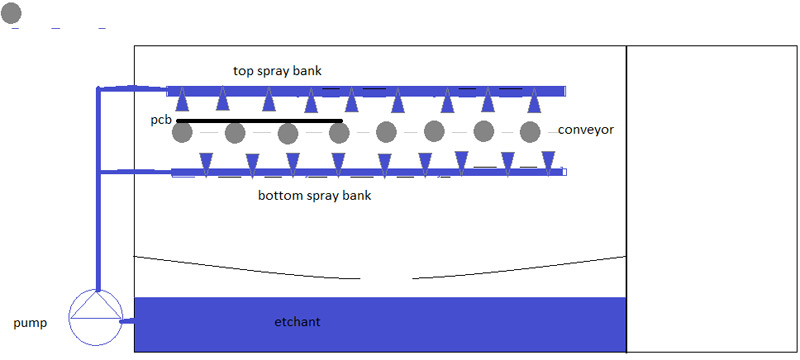
Undercut is relatively easy to explain in that when a copper sheet is chemically etched, it is done with a bank of spray nozzles and a proprietary etch solution. The board is driven through the etch chamber on a conveyor. As the solution hits the copper, it attacks it and leaves behind the tracks that are protected with either a plated etch resist or a photo imaged resist.
At the track edge, there is always an amount of copper removed under the resist, this is undercut.
If you can imagine you bed a paving slab onto sand and use a hose to wash away the excess around the side. You will always lose a bit of the sand at the edge of the slab even though you don’t point the jet directly at the side, where it undercuts. If the sand is 25mm thick, by the time you have washed it away you will lose say 20mm into the slab. If the sand is 50mm thick, by the time you are through it you will have washed away maybe 40mm. Well, copper behaves similarly, if it is 17 micron, the undercut will be significantly less than 70 micron.
 The thickness of the base copper+any plating divided by the amount of undercut is known as the etch factor.
What is the significance to board design you might ask? If you have a 0.25mm wide track in 35 micron copper and you need more current through it, increasing the copper thickness by 35 micron may be less effective than increasing the track width by 25 microns.
There is a host of influencing factors which need consideration. If the gap and track is say 0.2mm, then it will be very difficult to remove the copper between the tracks anyway but thicker base copper will have a bigger effect at these widths, take longer in the etch machine resulting in greater undercut.
If the tracks and gaps are 2.5mm, then the problem is reduced dramatically and the thicker base will have a positive effect.
Manufacturing etching challenges
If I outline some of the challenges of the process, it may help designers to understand why certain aspects of design cost more.
The solution
Most etching is carried out using an ammonia based etch solution. It is controlled carefully in temperature, pH(By extraction,) and copper loading, (the amount of copper held in solution.) The solution, when it is dosed in to the etch chamber, has zero copper in it. It is not an effective etchant at this point. Once it mixes with the solution in the chamber, it becomes very aggressive and attacks the base copper easily. The base copper goes into the solution but once it reaches 150 grammes per litre, its etching capability is all but gone. Generally, the process is controlled by a feed and bleed system. So, no matter how carefully the solution is controlled, there is always a variation in its etching capability. So now we know of 3 factors that effect the finished track width at etch. Temperature, pH, and copper in solution.
The equipment
Etch machines have not changed significantly in 30 years. There are generally a top and bottom bank of jets, spraying from a sump onto a board which is driven through on a conveyor using rubber wheels to allow the solution access to the board. There are several considerations again that are needed. On the top side, the etch hits the board, dissolves the copper but has nowhere to exit so sits over the copper that needs removing. The fresh etchant needs to blast through the spent etchant to do its job. This effect is known as puddling and slows the etch rate significantly. On the bottom, the fresh etch hits the board, does its job and falls away. This makes the bottom bank of jets much more efficient than the top. The speed through is the same for top and bottom so the only way to compensate it to reduce the pressure on the bottom bank. This does change the undercut characteristics.

If a PCB is designed so the complex tracks are on one side and say a ground plane on the other, as a rule, the boards would be fed in track side down to get the best results.
To prevent the copper laden etch from going to drain, the post etch chamber is normally fresh etchant which once sprayed onto the board drains into the etch sump hence doses the system. This is generally known as an anti pollution rinse.
This is by no means a comprehensive process control of etching document but more of an insight document to help designers understand the process and hence consider these factors to help reduce the cost of the board and give a more reliable product.
Next month: Photo mechanical imaging and electro plating, unless anyone wants to put something “under the eyeglass.”
